TPC Programming Model
On this Page
TPC Programming Model
TPC Program Inputs/Outputs
A TPC program can only accept tensor objects as its input/output vehicles. A tensor is a multidimensional array. A 1D tensor can be thought of as a simple C array. Matrices are two dimensional tensors, which can be either row major or column major. The TPC processor supports tensors with 1–5 dimensions.
To make TPC programming easier, the TPC programming language includes a dedicated, built-in tensor data type. Tensor variables are opaque handles used to access elements of the tensor data structure using cartesian coordinates. If the cartesian coordinates fall outside the tensor on a read operation, a special padding value is returned. The padding value is determined by the glue code.
If the cartesian coordinates of a write operation fall outside the written tensor, the write operation is culled by the memory control unit. The TPC vector units always align with dimension zero (dim0). On dim0 the write operation is partially culled if some values fall inside the tensor and some fall outside of it. A TPC program can address up to eight tensors in a single program. This set of tensors can be arbitrarily divided between input and output tensors. The TPC programming language specifies dedicated-access intrinsic functions to read/write data from the tensors (for example, v_f32_ld_tnsr_i/v_f32_st_tnsr_i).
General Limitations of TPC-C
Scalar variables can be assigned into a specific vector lane, or broadcasted to all vector data type lanes, but vector lane values cannot be assigned back into scalar variables.
// supported code
float a = 65;
float64 b = a;

// unsupported code:
float64 b ;
float a = b[44];
A TPC-C program can access at most 16 tensors overall. Any partition between input tensors and output tensors is supported. If the program uses printf, only 15 tensors can be used.
Index Space
The Gaudi ASIC has multiple TPC processors. Intel Gaudi introduced index spacing to effectively divide workloads between TPC processors. To achieve good workload distribution when writing a TPC program, you must define how the inputs/outputs of a TPC program can be partitioned into indivisible units of work. Defining a multiple dimension index space defines partitions. The index space may have one to five dimensions defined by the kernel writer depending on the dimensionality and sizes of the input/output tensors and the semantics of the operation itself.
For example, assume we want to write a program that performs elementwise add operations on two 2D tensors of size (3*192) with a single precision data type.
Since the VPU unit processes 64 single precision elements in one instruction, an adequate index space for such input would be a two-dimensional index space of size (3,3). A (3,3) sized index space would have nine members. Each member of the index space is responsible for processing 64 elements in the input/output tensors, as illustrated Fig. 26.
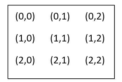
Figure 26 Values of Nine Index Space Members in a (3,3) Index Space
In this example, each member of the index space directly correlates to
64 members (elements) in the resulting tensor. The machinery around the TPC
may invoke the TPC program several times, each time with a different
contiguous subset of the index space. In our examples, the program may
be invoked only once for the entire index space (0,0)–(2,2), or it may
be invoked up to nine times, each time for a single index space member.
When program execution starts, the program should call built-in
functions get_index_space_offset and get_index_space_size to query which
subset of the index space it is invoked against (see example below). It then
uses this result to perform the actual computation. Each member of the
index space represents a unit of work that is executed on a single TPC
and is independent of other index space members. The index space
members can be executed at different times and on different TPC engines.
Therefore, you cannot assume any order of execution between
index space points or try to share data between them. You
can assume that each index space member will be invoked exactly once and
that all index space members will eventually be invoked.
void main(tensor inputA, tensor inputB, tensor outputC)

{
 int5 start = get_index_space_offset();
 int5 end = start + get_index_space_size();
 int5 targetCoord = { 0 };
 for(int i = start[0]; i < end[0]; i++)
 {
 targetCoord[1] = i;
 for (int j = start[1]; j < end[1]; j++)
  {
   targetCoord[2] = j;
   float64 a = v_f32_ld_tnsr(targetCoord,inputA);
   float64 b = v_f32_ld_tnsr(targetCoord,inputB);
   float64 c = a + b;
   f32_st_tnsr_i_v(targetCoord,outputC,c);
  }
 }
}
Depending on a variety of considerations, the machinery around the TPC may invoke the program several times. Each program invocation is called a program instance, and is invoked with a unique contiguous subset of the index space. Examples of several options that can call the program are as follows:
It may invoke the program only once with the following offset/size:
Offset (0,0), size (3,3)
It may invoke the program three times, once for each row of the tensor:
Offset (0,0), size (1,3)
Offset (1,0), size (1,3)
Offset (2,0), size (1,3)
It may invoke the program twice:
Offset (0,0), size (2,3)
Offset (2,0), size (1,3)
The execution model has two restrictions:
No member of the index space can be called twice.
All members of the index are addressed.
Index Space Mapping
When writing TPC, you can also define how the index space maps to each of the program’s input/output tensor elements. The pattern specifies for each member in the index space which tensor elements are read/written during its associated computation. The mapping is made from the index space values as input, to an Agronrange of element coordinates in each dimension and for each input/output tensor. This mapping intends to help the graph compiler improve the pipelining between MME and TPC.
This mapping, however, is not mandatory. You can skip this mapping by
flipping the allRequired flag and glue-code for the kernels glue code.
This prevents fine-grain pipelining between MME and TPC and enables a fully functional kernel.
Simple linear transformation does the mapping:
starta x + startb to enda x + endb. You
must define for each dimension of each input/output tensor
to which dimension of the index-space it maps, and to provide four
constants - starta, enda, startb, endb. x is the
index space member value as defined in Fig. 26.
Example:
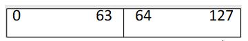
Figure 27 1D input tensor, 128 elements
Consider the function abs activated on a 1D single precision
tensor of size 128.
When writing glue code, you are more likely to choose a 1D index space of size 2,
since the array can be processed with two VPU operations. Index space
member (0) should be mapped to applying abs to elements 0-63 of the
vector, and index space member (1) should be mapped to applying abs to
elements 64-127 in the array.
The a/b constants for such use case would be:
starta = 64, startb = 0
enda = 64, endb = 63
The mapping between index space and tensors would be:
startF(x) = 64*x + 0
endF(x) = 64*x+63
When evaluating the first index space element (0)
startF(0) = 64*0 + 0 = 0
endF(0) = 64*0 + 63 = 63
When evaluating the second index space element (1)
startF(1) = 64*1 = 64
endF(1) = 64*1 + 63 = 127
A set of starta, enda,startb, endb is defined for each dimension of each input/output tensor of a kernel.
Full end-to-end examples can be found in the GitHub repo under:
/kernels/gaudi/filter_fwd_2d_bf16.c– TPC-C code/src/gaudi_src/filter_fwd_2d_bf16.cpp– Glue code/src/spatial_reduction_kernels.cpp– Glue code
Additional Considerations
Several program instances may execute concurrently, as there are several TPC processors in the accelerator. Sharing memory between index execution is only possible using ASO instructions.
The order of instance execution is not guaranteed.
Data Layout for Convolutional Neural Networks
Two allocations represent a tensor in memory – a contiguous slab of memory holding the tensor content, and a tensor descriptor holding stride and size values for each dimension.
For example, a tensor representing a row major matrix of size (3,10) of floats is represented by a 120‑byte array (3*10*4 bytes/element) and a 2D array holding the following values:
dim 0 (size =10, stride = 1)
dim 1 (size = 3, stride = 10)
The stride value represents the number of elements separating one member of the dimension to the next. The dimension whose stride value equals 1 is called the fastest changing dimension. The fastest changing dimension is always dimension 0 with TPC. Convolutional neural networks accept 3D, 4D tensors as input. Gaudi devices can only effectively support input tensors with an NHWC layout, meaning that only tensors whose channel component is the fastest changing and in dimension 0. A TPC program incorporated into CNNs should assume this layout.