Configure E2E Test in L2/L3 Switching Environment
On this Page
Configure E2E Test in L2/L3 Switching Environment
The E2E test can be configured to work with both L2 and L3 network setups. The instructions in this section describe the configuration process using an L3 switching example.
Creating E2E connectivity via L3 switches requires additional network and device configurations beyond those needed for L2 switching. This section describes the additional configuration requirements, how to obtain them, and how to configure the E2E test to utilize them.
A Layer 3 switch combines the functionalities of both a switch and a router. It serves as a switch to connect devices within the same subnet or virtual LAN, while also incorporating IP routing capabilities to function as a router. This allows it to support routing protocols, inspect incoming packets, and make routing decisions based on source and destination addresses. Layer 3 switch is commonly used for routing packets between different VLANs.
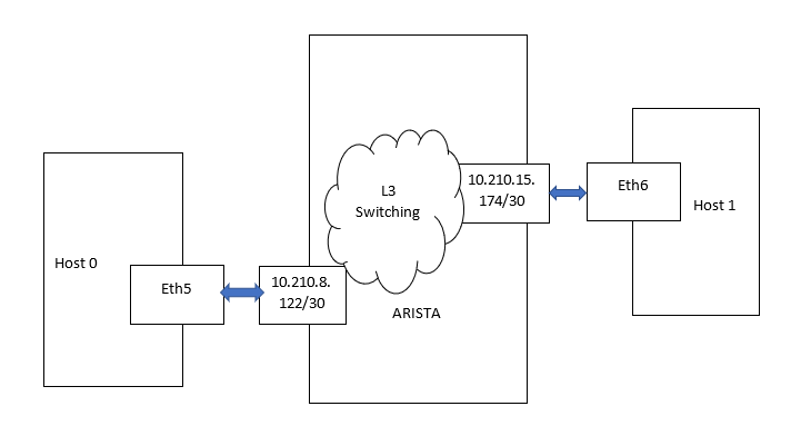
For example, Cluster07 in Intel® Tiber™ AI Cloud has Arista switches configured as Layer 3 switches. This configuration requires assigning an IP address to each Gaudi port
and using these addresses for communication between ports. Each Arista port is configured as its own subnet with a netmask of /30 or 255.255.255.252. This setup allows for four addresses in total, following
the standard configuration - a broadcast address, a network address, and two node addresses.
The Arista port itself is assigned the highest node address within the subnet. It is expected that the device connected to the port uses
the other available node address. The network 10.210.8.120/30 can include the following:
Network address: 10.210.8.120
Broadcast address: 10.210.8.123
Host IP range: 10.210.8.121 - 10.210.8.122
Arista port: 10.210.8.122
The IP Subnet Calculator can be used for the calculation.
Prerequisites
If not already installed, make sure to have the latest Intel Gaudi software stack installed as detailed in the Installation Guide.
Note
If you are not using the latest Intel Gaudi software stack, make sure to install the correct version.
Configuration
Obtaining Arista Port Information
On the Arista host, load the driver and bring up its interfaces:
Unload the drivers. The order depends on the version of the driver currently running:
sudo modprobe -r habanalabs && sudo modprobe -r habanalabs_cn && sudo modprobe -r habanalabs_ib && sudo modprobe -r habanalabs_en
sudo modprobe -r habanalabs_ib && sudo modprobe -r habanalabs_en && sudo modprobe -r habanalabs_cn && sudo modprobe -r habanalabs && sudo modprobe -r habanalabs_compat
Load the drivers:
sudo modprobe habanalabs_compat && sudo modprobe habanalabs && sudo modprobe habanalabs_cn && sudo modprobe habanalabs_en && sudo modprobe habanalabs_ib
Bring up the interfaces:
/opt/habanalabs/qual/gaudi3/bin/manage_network_ifs.sh --up
Assuming eth5 is the interface in which you want to connect to, run
sudo lldpcli:sudo lldpcli [lldpcli] # show neighbors ports eth5 ------------------------------------------------------------------------------- LLDP neighbors: ------------------------------------------------------------------------------- Interface: eth5, via: LLDP, RID: 15, Time: 0 day, 00:00:06 Chassis: ChassisID: mac 94:8e:d3:c8:52:69 SysName: 2b29u25n.idc9.habana-labs.com SysDescr: Arista Networks EOS version 4.26.4M running on an Arista Networks DCS-7060DX4-32 MgmtIP: 10.210.255.115 Capability: Bridge, on Capability: Router, on Port: PortID: ifname Ethernet22/7 PortDescr: no-alert 10.210.8.122/30 TTL: 120 -------------------------------------------------------------------------------
Obtaining Gaudi Port IP Information
Note
The numbers used in this section are examples only.
The Arista port is configured to show, in addition to other details, the following information:
MAC address: 94:8e:d3:c8:52:69
Port IP and netmask: 10.210.8.122/30
This information is used to determine the eth5 IP address (10.210.8.122/30) and the destination MAC address (94:8e:d3:c8:52:69). For example, to connect a device with port named eth5 to the above port/net, use address 10.210.8.121 as follows:
sudo ip addr add 10.210.8.121/30 dev eth5
sudo ifconfig eth5 up
The connectivity with Arista can be verified using ping 10.210.8.122. This provides another way to determine the Arista MAC address will be used as the destination MAC address in your configuration.
The address can be viewed using ARP:
arp
Address                  HWtype  HWaddress           Flags Mask            Iface
10.210.8.122             ether   94:8e:d3:c8:52:69   C                     eth5
To connect to a peer Gaudi port or an entire subnet, add the appropriate entry to the routing table:
sudo ip route add 10.210.0.0/16 via 10.210.8.122 dev eth5
Creating IP Connectivity Between the Peer Ports
The below steps assume the following setup:
On Host0, perform the following:
Unload the drivers. The order depends on the version of the driver currently running:
sudo modprobe -r habanalabs && sudo modprobe -r habanalabs_cn && sudo modprobe -r habanalabs_ib && sudo modprobe -r habanalabs_en
sudo modprobe -r habanalabs_ib && sudo modprobe -r habanalabs_en && sudo modprobe -r habanalabs_cn && sudo modprobe -r habanalabs && sudo modprobe -r habanalabs_compat
Load the drivers:
sudo modprobe habanalabs_compat && sudo modprobe habanalabs && sudo modprobe habanalabs_cn && sudo modprobe habanalabs_en && sudo modprobe habanalabs_ib
Bring up the interfaces:
/opt/habanalabs/qual/gaudi3/bin/manage_network_ifs.sh --up
Run
lldpcli show neighbors ports eth5to obtain the ChassisID: mac 94:8e:d3:c9:88:2d and PortDescr: no-alert 10.210.8.122/30.Assign the IP address (10.210.8.121/30):
sudo ip addr add 10.210.8.121/30 dev eth5
To check if the IP is assigned successfully, run the following command:
ping 10.210.8.122
Add a route to all Arista subnets. This can be done per subnet in case there is more than one port:
sudo ip route add 10.210.0.0/16 via 10.210.8.122 dev eth5
On Host1, perform the following:
Unload the drivers. The order depends on the version of the driver currently running:
sudo modprobe -r habanalabs && sudo modprobe -r habanalabs_cn && sudo modprobe -r habanalabs_ib && sudo modprobe -r habanalabs_en
sudo modprobe -r habanalabs_ib && sudo modprobe -r habanalabs_en && sudo modprobe -r habanalabs_cn && sudo modprobe -r habanalabs && sudo modprobe -r habanalabs_compat
Load the drivers:
sudo modprobe habanalabs_compat && sudo modprobe habanalabs && sudo modprobe habanalabs_cn && sudo modprobe habanalabs_en && sudo modprobe habanalabs_ib
Bring up the interfaces:
/opt/habanalabs/qual/gaudi3/bin/manage_network_ifs.sh --up
Run
lldpcli show neighbors ports eth6to obtain theChassisID: mac 94:8e:d3:c8:52:69andPortDescr: no-alert 10.210.15.174/30.Assign the IP address (10.210.15.173/30) to the eth6 interface:
sudo ip addr add 10.210.15.173/30 dev eth6
To check if the IP is assigned successfully, run the following command:
ping 10.210.15.174
Add a route to all Arista subnets. This can be done per subnet in case there is more than one port:
sudo ip route add 10.210.0.0/16 via 10.210.15.174 dev eth6
Ping should now work between Host0:Port5 and Host1:Port6. To verify that the assigned IP address is routed correctly to the other host, run the following commands:
On Host0, run:
ping 10.210.15.173
On Host1, run:
ping 10.210.8.121
Generating a gaudinet.json Example
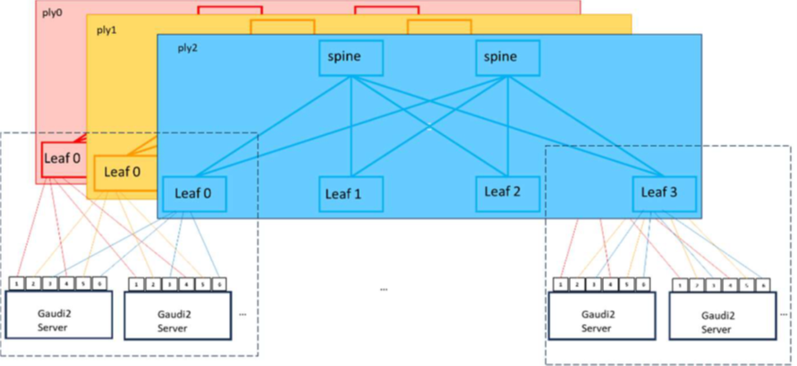
The below example assumes a reference network design with a three-tier leaf-spine topology. Each Gaudi 3 server is connected to all three tiers via its six QSPF-DD ports:
Ports 1&4 to ply0
Ports 2&5 to ply1
Ports 3&6 to ply2
The /etc/habanalabs/gaudinet.json file is required on the Gaudi 3 server side to configure network settings for Layer 3 (L3) routes. This file should include the Gaudi NIC MAC address, IP address,
subnet mask, and gateway MAC address for each of the 24 NICs in the following format:
{
   "NIC_NET_CONFIG": [
     {
         "NIC_MAC": "00:1A:2B:3C:4D:5E",
         "NIC_IP": "192.168.1.10",
         "SUBNET_MASK": "255.255.255.0",
         "GATEWAY_MAC": "00:1A:2B:3C:4D:5F"
      },
      {
         "NIC_MAC": "00:1A:2B:3C:4D:6E",
         "NIC_IP": "10.0.0.20",
         "SUBNET_MASK": "255.0.0.0",
         "GATEWAY_MAC": "00:1A:2B:3C:4D:6F"
     },
     …
   ]
}
Each object inside the NIC_NET_CONFIG array corresponds to the configuration of a single NIC.
The following table describes each object used in the /etc/habanalabs/gaudinet.json:
Object |
Type |
Description |
Format Example |
|---|---|---|---|
NIC_MAC |
String |
NIC MAC address. This field is required and must follow the standard MAC address format. |
00:1A:2B:3C:4D:5E |
NIC_IP |
String |
IP address assigned to the NIC. Must be in a valid IPv4 or IPv6 format. |
192.168.1.10 |
SUBNET_MASK |
String |
Subnet mask defining the network’s address range. |
255.255.255.0 |
GATEWAY_MAC |
String |
MAC address of the gateway through which the NIC routes its traffic. This field must follow the standard MAC address format. |
00:1A:2B:3C:4D:5F |
To generate the gaudinet.json file, perform the following:
From hl-smi, retrieve the mapping of Gaudi module ID to bus ID by running the following command:
hl-smi -Q module_id,bus_id -f csv,noheader
The first column in the output is the Gaudi module ID, while the second column is the bus ID as shown in the following example:
6, 0000:9a:00.0
2, 0000:33:00.0
3, 0000:34:00.0
7, 0000:9b:00.0
4, 0000:b3:00.0
0, 0000:4d:00.0
1, 0000:4e:00.0
5, 0000:b4:00.0
Obtain three MAC addresses (one address for each ply) for each Gaudi module:
Replace the bus_id in the following command with the bus_id retrieved in Step 1:
cat /sys/bus/pci/drivers/habanalabs/{bus_id}/net/\*/address \| sort
To get the three MAC addresses for Gaudi module 0 in the above example, run the following:
cat /sys/bus/pci/drivers/habanalabs/0000:4d:00.0/net/\*/address \| sort
b0:fd:0b:d9:22:4d #MAC for ply0
b0:fd:0b:d9:22:5b #MAC for ply1
b0:fd:0b:d9:22:5c #MAC for ply2
Repeat the steps for Gaudi modules 1 through 7 to generate a list comprising of 24 lines in total.
Assign the NIC IP addresses. Use the following formula to determine the IP address format:
10.(starting_second_octect+ply_id).(leaf_switch_id).(1+port_seq_idx4)/30
The following table describes each parameter included in an IP address:
Parameter
Description
starting_second_octet
User’s choice
ply_id
0, 1, 2
leaf_switch_id
ID of the connected leaf switch
port_seq_id
The sequence number of the 100Gb/s interfaces across all servers connected to the same leaf switch. Each server has 8 interfaces connected to each of the 3 leaf switches, and the current server may not be the first server connected to a leaf switch.
/30 netmask
Subnet mask is 255.255.255.252 for point-to-point /30 network.
Example for Server 1:
For the first server, which is connected to the lowest-numbered switch port facing the Gaudi servers and attached to the first leaf switch, the IP address is assigned to the NIC ply0 on Gaudi module 0 using the following formula:
10.(208+0).(0).(1+0x4)/30 = 10.208.0.1/30.Example for Server 2:
For the second server, which is connected to the second leaf switch, the IP address is assigned to the NIC ply1 in Gaudi module 2 using the following formula:
10.(208+1).(1).(1+10x4)/30 = 10.209.1.41/30. Theport_seq_idis 10 because the first server is connected to the first eight Gaudi-facing interfaces on this switch, and the current NIC is in Gaudi module 2, resulting in 8+2 = 10.Pull the gateway MAC address which is the MAC address of the connected switch. It can be pulled either from the switch or the
lldpctl showneighborcommand on the server.
Generating a gaudinet.json Using Intel Network Operator
The Intel Network Operator discover tool is used to identify and configure
network interfaces of the Gaudi devices. It can be built and run using CLI or Docker.
CLI Installation
Install Go 1.23 or newer by following the official instructions at https://go.dev/doc/install.
Install
libpcap-dev:sudo apt install libpcap-dev
Clone the
network-operatorrepository:git clone https://github.com/intel/network-operator.git
Build the tool:
cd network-operator
go mod vendor
make build
Run the tool:
sudo mkdir -p /etc/habanalabs
sudo ./bin/discover --gaudinet /etc/habanalabs/gaudinet.json --wait 120s -v 3 --configure --mtu 8000
Docker Installation
Run the tool using Docker:
docker run --privileged --rm --network=host -v /etc/habanalabs:/etc/habanalabs:rw intel/intel-network-linkdiscovery:1.0.0 --gaudinet /etc/habanalabs/gaudinet.json --wait 120s -v 3 --skip_headers --configure --mtu 8000
Output example:
sudo ./bin/discover --gaudinet /etc/habanalabs/gaudinet.json --wait 120s -v 3 --skip_headers --configure --mtu 8000
Started LLDP discovery for 'eth3'...
Started LLDP discovery for 'eth4'...
Started LLDP discovery for 'eth5'...
libibverbs: Warning: couldn't load driver 'libvmw_pvrdma-rdmav34.so': libvmw_pvrdma-rdmav34.so: cannot open shared object file: No such file or directory
^[[AConfiguring interfaces...
Configured address and route 10.208.6.29/30 for interface 'eth4'
Configured route 10.208.0.0/16 gateway 10.208.6.30 for interface 'eth4'
Configured address and route 10.209.6.17/30 for interface 'eth5'
Configured route 10.209.0.0/16 gateway 10.209.6.18 for interface 'eth5'
Configured address and route 10.210.6.25/30 for interface 'eth3'
Configured route 10.210.0.0/16 gateway 10.210.6.26 for interface 'eth3'
Configured 3 of 3 interfaces
Interface 'eth5' up|broadcast|multicast:
Configured addresses: 10.209.6.17/30(matches lldp) fe80::6a93:2eff:fe0c:3752/64
Peer MAC address: ec:8a:48:f3:5a:81
Peer LLDP address: 10.209.6.18
Local /30 LLDP address: 10.209.6.17
Interface 'eth3' up|broadcast|multicast:
Configured addresses: 10.210.6.25/30(matches lldp) fe80::6a93:2eff:fe0c:374d/64
Peer MAC address: ec:8a:48:f3:8d:49
Peer LLDP address: 10.210.6.26
Local /30 LLDP address: 10.210.6.25
Interface 'eth4' up|broadcast|multicast:
Configured addresses: 10.208.6.29/30(matches lldp) fe80::6a93:2eff:fe0c:374e/64
Peer MAC address: a4:3f:68:3d:0b:2d
Peer LLDP address: 10.208.6.30
Local /30 LLDP address: 10.208.6.29
Generating a gaudinet.json Using LLDP or DHCP Example
In addition to manually retrieving MAC addresses and IP configuration details, you can automate the generation of the gaudinet.json file using LLDP queries or DHCP.
A reference example of LLDP-based configuration is provided in the vault.
In this example, the l3-routes binary is used to perform LLDP queries.
The example must be modified to match the specific network environment and requirements. After making the necessary adjustments, copy
the l3-routes binary to /usr/bin/l3-routes.
When the manage_network_ifs.sh --up command is run, it verifies whether /usr/bin/l3-routes exists and executes the binary if found.
If all ports are operational, the binary automatically generates the /etc/habanalabs/gaudinet.json file.
Priority Flow Control (PFC)
If degraded performance is observed, check the switch counters for dropped packets. If packet loss is detected, enabling PFC (Priority Flow Control) may be beneficial. Examples of commands and configurations are included in Arista EOS.
To check packet loss on the switch, use the following command:
show interface counter queue
PFC/Buffer Configuration in Switch
To configure PFC/buffer in the switch, perform the following steps:
Add the following lines to the switch global configuration to adjust the buffer settings. Note that the threshold and headroom values provided are specific to the Arista 7060-DX4-32 and may vary for other switch models.
platform trident mmu queue profile PFC_Profile
ingress threshold 1
ingress headroom 165100
platform trident mmu queue profile PFC_Profile apply
For each interface, add the following lines to enable PFC in its configuration:
qos trust dscp
priority-flow-control on
priority-flow-control priority 0 no-drop
priority-flow-control priority 1 no-drop
priority-flow-control priority 2 no-drop
priority-flow-control priority 3 no-drop
uc-tx-queue 2
no priority
uc-tx-queue 3
no priority
The below examples present a full interface configuration.
Example 1:
interface Ethernet1/1
mtu 9198
speed 400g-8
error-correction encoding reed-solomon
no switchport
ip address 10.208.128.1/30
qos trust dscp
priority-flow-control on
priority-flow-control priority 0 no-drop
priority-flow-control priority 1 no-drop
priority-flow-control priority 2 no-drop
priority-flow-control priority 3 no-drop
uc-tx-queue 2
   no priority
uc-tx-queue 3
   no priority
Example 2:
interface Ethernet2/1
mtu 9198
speed 100g-2
error-correction encoding reed-solomon
no switchport
ip address 10.208.0.2/30
qos trust dscp
priority-flow-control on
priority-flow-control priority 0 no-drop
priority-flow-control priority 1 no-drop
priority-flow-control priority 2 no-drop
priority-flow-control priority 3 no-drop
uc-tx-queue 2
   no priority
uc-tx-queue 3
   no priority
Enable PFC in Gaudi Server
PFC should also be enabled in servers for the flow control mechanism to function effectively.
To enable PFC, run the following command:
/opt/habanalabs/qual/gaudi3/bin/manage_network_ifs.sh --set-pfc
To verify that the PFC is enabled, run the following command:
/opt/habanalabs/qual/gaudi3/bin/manage_network_ifs.sh --check-pfc
You should receive output similar to the following, indicating enabled=15.
check_pfc 'enp0n0'

enabled=15

check_pfc 'enp0n1'

enabled=15
Disable PFC in Gaudi Server
To disable PFC, run the following command:
/opt/habanalabs/qual/gaudi3/bin/manage_network_ifs.sh --unset-pfc
You should receive output similar to the following, indicating enabled=0.
check_pfc 'enp0n0'

enabled=0

check_pfc 'enp0n1'

enabled=0
Note
You may use the ip link set enpXXX up command if the network interface does not come up automatically for any reason.